How to Choose the Right Circuit Control Components?

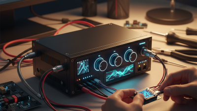
Choosing the right circuit control components begins with understanding the system, not browsing a product catalog. A relay, switch, sensor, fuse, contactor, or programmable controller may appear suitable on paper. Their real performance depends on voltage, current, load type, switching frequency, ambient temperature, and installation space. A motor load behaves differently from an LED circuit. A dusty factory cabinet also demands more protection than a clean laboratory bench.

Grace Hopper, a pioneering computer engineer, offered a useful warning: “The most dangerous phrase in the language is, ‘We’ve always done it this way.’” Her words fit circuit control decisions closely. Familiar components can still create hidden weaknesses. Check the datasheet line by line. Confirm contact ratings, inrush current, insulation strength, response time, and expected service life. Small details matter.

Reliability also requires evidence. Look for recognized certifications, traceable specifications, and clear manufacturer support. Test the selected component under realistic conditions, including heat, vibration, repeated switching, and abnormal loads. A device that works during a short bench test may fail after months of daily operation. That possibility deserves attention.

There is no perfect selection method. Engineers sometimes prioritize price too early, then discover higher wiring, replacement, or downtime costs. A better approach compares total operating risk, maintenance access, safety margins, and future expansion. The best circuit control solution is not always the most powerful component. It is the component that performs predictably, fits the application, and remains understandable when someone must troubleshoot it at 2 a.m.
How to Choose the Right Circuit Control Components?

Define the Role of Circuit Control Components in Electrical Systems

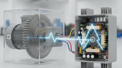
Circuit control components define how electrical energy is started, stopped, protected, and redirected. They are not merely switches. A circuit breaker interrupts abnormal current, while a contactor manages repeated load switching. Relays translate a small control signal into a larger operating action. Sensors add feedback, helping controllers detect temperature, pressure, position, or overload. Together, these devices create the system’s decision-and-response layer.

Selection begins with function, not catalog appearance. Engineers should identify voltage, current, fault level, duty cycle, enclosure conditions, and required isolation. IEC 60947-4-1 addresses low-voltage contactors and motor starters, while IEC 60269 covers low-voltage fuses. These standards make ratings comparable, but they do not replace application testing.

23%

The U.S. Department of Energy reports that motor-driven equipment represents about 23% of total U.S. electricity consumption.

That figure gives control decisions practical weight. Poor coordination can create nuisance trips, downtime, or dangerous restart behavior.

The IEA’s Electricity 2024 report projected global electricity demand growth of 3.4% annually through 2026. More electrified loads mean more switching cycles and more heat inside enclosures. Thermal spacing matters. A smaller enclosure may pass a paper calculation yet fail during a hot shift.

Field inspections often expose loose terminals, mismatched ratings, and undocumented changes. I would also question automatic designs that lack manual isolation or clear fault indication. That is an imperfect choice, but safer engineering often starts by admitting what the drawing does not show.

Identify Key Electrical Requirements Before Choosing Components

How to Choose the Right Circuit Control Components?

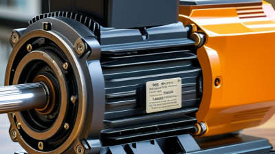
Before choosing circuit control components, identify the electrical requirements clearly. Record the system voltage, operating current, frequency, and whether the circuit uses AC or DC. Check the load type, because motors, heaters, and solenoids behave differently during switching. A motor may draw several times its rated current at startup. Ignoring that detail can damage contacts quickly.

Review the required switching frequency, control method, and expected service life. Determine whether the component must provide isolation, overload protection, or emergency disconnection. Also examine the installation environment. Dust, moisture, vibration, heat, and limited space can change the correct selection. Compare datasheet ratings with measured conditions, not assumptions. In field inspections, a component often appears suitable until ambient temperature reduces its current capacity. That mistake is easy to make. It is also expensive.

Tips: Create a simple requirement sheet before comparing parts. Include nominal voltage, maximum current, inrush current, fault level, operating temperature, enclosure rating, and terminal size. Confirm compatibility with the control signal and wiring method. Check recognized safety requirements for your region, then verify clearances and protection coordination. If measurements are uncertain, test the circuit under controlled conditions. A practical review by a qualified electrician or engineer can reveal missing details. Even experienced teams occasionally select components from incomplete data. Rechecking the assumptions is worthwhile.

How to Choose the Right Circuit Control Components? - Identify Key Electrical Requirements Before Choosing Components
Electrical Requirement What to Determine Typical Values or Design Range Potential Component Type Selection Guidance
System Voltage Nominal voltage, allowable variation, and whether the circuit uses AC or DC. 5 V, 12 V, 24 V, 48 V DC; 120 V or 230 V AC Power relay, contactor, solid-state relay, circuit breaker, control switch Select a component with a rated voltage equal to or higher than the maximum continuous operating voltage.
Load Current Normal operating current and the highest continuous current expected under full load. Control circuits: below 1 A; small loads: 1–10 A; power loads: above 10 A Fuse, circuit breaker, relay, contactor, power semiconductor Use the continuous current rating with an appropriate design margin; verify terminal and conductor ratings as well.
Inrush or Starting Current Temporary current drawn when motors, transformers, lamps, capacitors, or power supplies start. Often 2–10 times the steady-state current, depending on the load Motor-rated contactor, time-delay fuse, motor circuit breaker, soft starter, inrush limiter A component rated only for resistive loads may fail when used with inductive or capacitive loads.
Load Characteristics Whether the load is resistive, inductive, capacitive, motor-driven, or electronically controlled. Resistive heating, inductive coils, motors, transformers, LED drivers, switching supplies General-purpose relay, motor contactor, solid-state relay, triac, MOSFET, IGBT Check the component's utilization category, switching technology, voltage type, and permissible load category.
Switching Frequency How often the circuit will turn on and off during normal operation. Occasional switching: below 1 cycle/min; frequent switching: several cycles/min or higher Electromechanical relay, contactor, solid-state relay, transistor switch Electromechanical contacts are suitable for low to moderate switching rates; solid-state devices are preferred for high-cycle operation.
Isolation Requirement Whether the control signal must be electrically separated from the load circuit. Common isolation levels range from hundreds of volts to several kilovolts, depending on construction Electromechanical relay, optocoupler, isolated solid-state relay, isolation amplifier Verify working voltage, isolation voltage, creepage, clearance, and insulation category rather than relying on isolation voltage alone.
Protection and Interrupting Capacity Fault current, short-circuit level, overcurrent behavior, and required disconnection speed. Interrupting ratings commonly range from a few hundred amperes to several kiloamperes Fuse, miniature circuit breaker, molded-case circuit breaker, current limiter The interrupting rating must meet or exceed the prospective short-circuit current at the installation point.
Control Signal Coil or gate voltage, signal current, logic level, polarity, and control interface. 3.3 V or 5 V logic; 12 V or 24 V control circuits; AC control voltages also possible Relay module, contactor, MOSFET switch, optocoupler, driver circuit Confirm pickup and dropout limits, input current, reverse-polarity protection, and compatibility with the controller output.
Operating Environment Ambient temperature, humidity, dust, vibration, altitude, and exposure to chemicals or moisture. Typical industrial temperature range: approximately −20°C to +55°C; wider ranges require verification Industrial relay, sealed relay, enclosed contactor, rugged solid-state switch Derate current at elevated temperature and select the required enclosure or ingress-protection level for the installation.
Heat Dissipation Power loss generated by conduction, switching, coils, or semiconductor leakage. Solid-state devices may dissipate approximately 1–2 W per ampere depending on voltage drop Solid-state relay, MOSFET, IGBT, power contactor, heat sink Calculate junction or case temperature and provide a heat sink, ventilation, or thermal protection when necessary.
Service Life Required electrical cycles, mechanical cycles, maintenance interval, and acceptable failure rate. Electromechanical service life varies widely; solid-state devices have no mechanical contact wear Relay, contactor, solid-state relay, electronic switch Compare electrical life under the actual load with mechanical life; arcing, inrush, and switching frequency strongly affect contact life.
Safety and Compliance Required insulation, touch protection, emergency disconnection, grounding, and applicable electrical standards. Requirements depend on supply voltage, installation type, equipment category, and local regulations Safety relay, emergency-stop contactor, circuit breaker, fuse, residual-current device Use certified components appropriate for the application and verify coordination between protective, switching, and control devices.

Compare Component Types, Ratings, and Control Functions

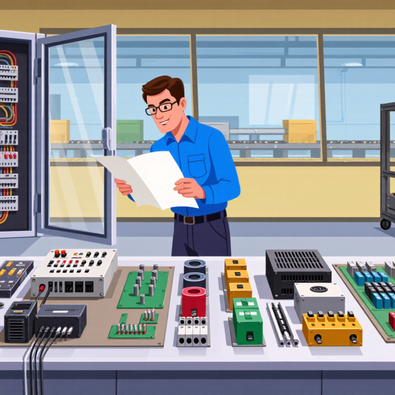
Choosing circuit control components starts with the control function, not the catalog shape. A manual switch suits simple, visible isolation. A relay handles low-power signals and separates control from load circuits. A contactor is better for frequent motor switching and higher currents. Solid-state devices switch quietly and quickly, but heat management becomes critical. Circuit breakers protect conductors while providing resettable interruption. Fuses respond reliably, although replacement time can complicate maintenance. Keep the purpose clear.

Compare ratings line by line. Check working voltage, continuous current, interrupting capacity, and AC or DC suitability. Motor loads demand attention to inrush current, not only the nameplate current. A 10-amp resistive rating may not support a 10-amp motor. Verify coil voltage, contact arrangement, poles, insulation rating, and switching frequency. For outdoor panels, review enclosure protection and temperature limits. Small details matter.

In field checks, I measure actual load current and inspect terminal temperature after operation. I also test the control circuit during a fault simulation, where permitted by site procedures. A component that works on the bench may fail beside vibration, dust, or voltage dips. A neat selection table can still mislead. I once focused too heavily on current rating and overlooked inrush. That mistake changed my checklist. Leave service space, label conductors, and confirm protective coordination with equipment documentation. If ratings conflict, stop and investigate. Guessing is not a control strategy.

Evaluate Safety, Compatibility, Reliability, and Installation Needs

How to Choose the Right Circuit Control Components?

Evaluate safety, compatibility, reliability, and installation needs before selecting circuit control components. Safety must lead the decision. The Electrical Safety Foundation International reported 126 workplace electrical fatalities and over 2,000 electrical injuries in 2020. These figures show why protective devices need correct voltage, current, and interrupting ratings. A component should also match the system’s insulation level and fault conditions. Small rating mistakes can create serious consequences.

Compatibility goes beyond fitting the enclosure. Check control voltage, terminal spacing, conductor size, switching frequency, and communication requirements. Consider heat, moisture, vibration, dust, and available maintenance space. The International Energy Agency reported that global electricity demand grew by about 6% in 2021, increasing pressure on electrical infrastructure and control systems. More connected equipment can also introduce unexpected coordination problems. Test the complete circuit, not only the individual device.

Reliability depends on documented performance and disciplined installation. EPRI estimated that power disturbances cost the U.S. economy between $119 billion and $188 billion annually. Proper suppression, grounding, separation, and overload protection can reduce avoidable failures. Yet field experience suggests a common weakness: installers often focus on the component and overlook the wiring path. That is not always enough. Review technical files, verify torque values, label circuits clearly, and schedule inspections after commissioning. A perfect selection can still fail when installation details are treated as minor.

Select Components Based on Performance, Cost, and Future Maintenance

Choosing circuit control components requires more than matching voltage and current ratings. Start with real operating conditions, including load type, switching frequency, ambient temperature, and available space. A component may pass a laboratory test but fail inside a warm, crowded control cabinet. Check response time, electrical endurance, insulation strength, and protection features. These details often matter more than a low purchase price.

Cost should include installation, testing, energy use, replacement parts, and downtime. A cheaper relay can become expensive if its contacts wear quickly or its terminals loosen during vibration. I once focused too heavily on the initial price and underestimated maintenance access. That decision worked at first, but troubleshooting later took much longer than expected. This is worth remembering. The lowest quote is not always the lowest total cost.

Tips: Compare lifecycle cost, not only unit price. Leave clear space around heat-producing components. Choose parts with accessible terminals and readable markings. Keep technical documents and replacement specifications in a controlled file. Before approval, test the component under realistic load conditions. A small pilot test can expose noise, heating, or delayed switching. Also, review future changes. A control system may need extra inputs, higher loads, or updated safety functions. Selecting adjustable and widely supported components can reduce redesign work, although excessive flexibility may increase complexity. Use only features that serve a clear purpose.

How to Choose the Right Circuit Control Components?

Select components based on performance, cost, and future maintenance.

The chart uses a 0–100 comparative index derived from typical engineering characteristics of generic component technologies. Performance reflects switching speed and power-handling capability, cost reflects the relative total implementation cost, and maintenance reflects expected service needs, wear, and thermal reliability. Higher scores indicate a more favorable choice for that criterion.

Go to Top