What Are the Top 10 Motor Control Circuit Types?
Choosing the right motor control circuit begins with understanding how a motor starts, stops, reverses, and responds to abnormal conditions. In practical panels, the difference may appear in a small detail: a 24-volt control transformer, an overload relay, or an auxiliary contact holding a starter closed. These components influence safety, maintenance, energy use, and troubleshooting time. Technicians often identify faults by listening for contactor chatter, checking voltage at each terminal, and comparing readings with the wiring diagram. Small clues matter.
This guide examines the top 10 motor control circuit types used in industrial, commercial, and automation applications. It covers direct-on-line starters, reversing starters, star-delta arrangements, two-speed controls, soft starters, and variable frequency drive systems. Each design has a different purpose, limitation, and installation requirement. Some suit simple pumps, while others support conveyors, fans, or precise production equipment. Standards and manufacturer instructions remain essential references, especially for isolation, overload protection, grounding, and emergency stopping. Real installations are rarely perfect. Older panels may contain undocumented modifications, mismatched labels, or components replaced without updating the drawing. That reality deserves attention. The list therefore should not be treated as a universal ranking. Application, motor data, duty cycle, available fault protection, and operator needs must guide the final choice. A reliable circuit is not merely one that runs the motor. It should also make faults visible, testing practical, and future maintenance safer.
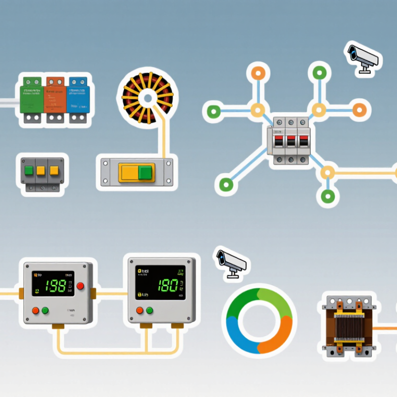
Motor Control Circuits: Purpose, Components, and Operating Principles
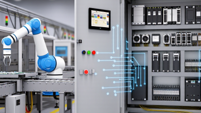
Motor control circuits manage how an electric motor starts, stops, changes direction, and responds to faults. Their power path carries current to the motor, while a control path sends operating commands. Common components include contactors, overload relays, fuses or circuit breakers, push buttons, sensors, and control wiring. Each has a job. A contactor switches power; an overload relay trips when sustained excess current threatens the motor.
Ten common circuit types include direct-on-line, reversing, star-delta, soft-starter, variable-frequency-drive, two-wire, three-wire, jog, interlocking, and sequential control. Direct-on-line circuits apply full supply voltage through a contactor. Reversing circuits swap two phases using interlocked contactors, preventing both directions from engaging together. Star-delta circuits reduce starting current, but they suit only compatible motors and loads. Soft starters ramp voltage; variable-frequency drives adjust both frequency and speed. The names describe different approaches, not ten entirely separate technologies.
In a typical three-wire circuit, a start button energizes a contactor coil, and an auxiliary contact holds it after the button is released. A stop button or overload trip opens the control path, dropping out the contactor. It is a simple arrangement, yet wiring errors still happen. Labels, a clear schematic, and tested overload settings matter. Actual design depends on motor ratings, load behavior, supply conditions, and the required stopping method. Never assume a circuit is safe because it works once.
Top 10 Motor Control Circuit Types
This chart compares the distinct operating states in a representative configuration of each circuit type. Counts are illustrative: actual states depend on the motor, controls, and system design.
Reading the chart: A basic start/stop circuit has two states—stopped and running. A three-speed circuit has four—stopped and three speed selections. Interlocks and safety devices can add further behavior.
Basic Starting and Stopping Circuits for Motor Operation
A motor control circuit does more than switch power on and off. It gives the operator a clear way to start and stop a motor while allowing protective devices to interrupt operation. A common arrangement uses a normally closed Stop button, a normally open Start button, and a contactor coil. Small contacts matter.
When the Start button is pressed, current energizes the coil and closes the contactor’s main contacts. An auxiliary contact then closes across the Start button, keeping the coil energized after the operator releases it. This is called a holding, or seal-in, circuit. Pressing Stop opens the control path, drops out the contactor, and disconnects the motor from its supply.
An overload relay’s normally closed contact is commonly placed in series with the coil, so an overload can stop the motor. In a typical three-wire circuit, a power interruption releases the contactor; the motor usually will not restart until Start is pressed again. That behavior can reduce unexpected restarts, but the complete system still needs a risk-based review. Real panels can have unclear labels, and that detail is easy to overlook. Before inspection or wiring, isolate the supply and verify it is de-energized; qualified personnel should follow the applicable equipment instructions.
Reversing, Jogging, and Interlocking Control Arrangements
Reversing, jogging, and interlocking circuits address different motion needs, yet each depends on predictable starts and stops. The U.S. Department of Energy’s 2014 Industrial and Commercial Motor System Market Assessment Report estimates motor-driven systems use about 68% of U.S. manufacturing electricity. Small control decisions deserve careful review.
In a reversing starter, two contactors exchange two motor phases. Mechanical and electrical interlocks prevent both contactors from closing together. During commissioning, check that the auxiliary contact opens the opposite coil circuit before direction changes. A brief stop may also be needed when the machine carries significant inertia. Still, field conditions are messier.
Jogging runs the motor only while an operator holds a button, useful for positioning a conveyor or machine axis. Repeated inching adds heat to motors and contacts, so duty cycle and overload settings matter. The International Energy Agency’s 2011 analysis estimates motor-driven systems account for roughly 45% of global electricity use. That figure depends on the report’s scope and year. IEC 60947-4-1 covers contactors and motor-starters; designers should also verify fault protection, restart behavior, and interlock operation against the actual machine. Interlocks can fail, too.
Electronic, Variable-Speed, and Safety-Based Control Circuits
What Are the Top 10 Motor Control Circuit Types?
Electronic, Variable-Speed, and Safety-Based Control Circuits
Motor control circuits range from simple direct-on-line starters to programmable, safety-focused systems. Ten common types include direct-on-line, forward-reverse, jogging, star-delta, autotransformer, soft-starter, variable-frequency drive, servo, PLC-based, and safety-relay circuits. The right choice depends on the motor, load, required speed range, and stopping behavior. A pump may need gentle acceleration, while a conveyor may require precise speed control and monitored stopping. The International Energy Agency’s Energy Efficiency 2023 report estimates that electric motor systems use about 45% of global electricity. Efficient control matters. Yet a variable-speed drive is not automatically the best option; poor setup can waste energy or create mechanical stress.
Safety-based circuits add another layer. Emergency-stop devices, interlocks, and safety relays can help prevent hazardous motion, but their design must match the machine’s risk assessment. IEC 60204-1 covers electrical equipment of machinery, while ISO 13849-1 addresses safety-related control systems. A standard reference is not a substitute for competent engineering. A tidy schematic can still hide a weak point, especially when sensors, contactors, and restart behavior are overlooked.
Tips: Confirm motor current, load inertia, and required stopping time before selecting a circuit. Test fault response and restart behavior under realistic conditions. Record the settings. Small omissions are easy to miss.
 Skip to content